The Fab Academy 2014
Digital Fabrication Laboratory. Department of Architecture.
Institute of Technology. EPS-CEU San Pablo CEU University
Adolfo Gutiérrez Sánchez
Architect
The Fab Academy 2014 Digital Fabrication Laboratory. Department of Architecture. Institute of Technology. EPS-CEU San Pablo CEU University |
Adolfo Gutiérrez Sánchez Architect |
|||
| Home | Portfolio | Files | ||
| FINAL PROJECT |
| IDEAS OF THE FINAL PROJECT | ||
| The aim of the FabLab course is to accomplish a Final Project along the course, using all the learnt concepts in the following classes.
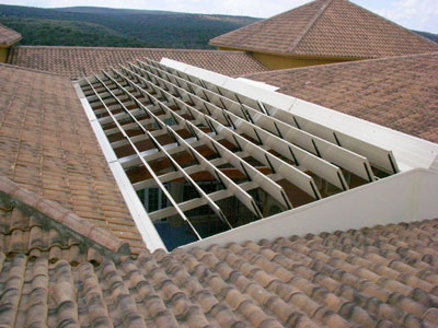
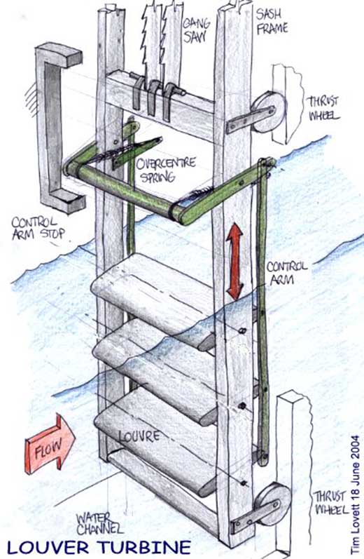
The idea of the Final Project is to build a reactive roof of a house, that reacts when sun is more vertical to shade the covered space. and to open as much as possible when the sun is softer so the light comes in and during the coldest part of the day the space maintains heated. A retractable roof is a kinetic architectural element where the roof can be mechanichally moved with a motor system that can even be moved with solar radiation. There are several applications of a project like this in architecture. During the past years, domotic architecture in relation with sustainability are the most powerful fields to study in architecture and construction. This new architecture appearing these days is the consequence of the bioclimatic change happening now, where the energy have to be saved as much as possible, and the houses of the future become more efficient. The final project presentation has to develop several assignments and the complete design and constructional elements of the whole model, including the programming system and sensoring as the creation of the pieces that conform the structure, living space and the roof itself. |
 |
|
  |
One of the targets of the project is not to become a very fixed element, but an element that can be developed more and more, and can be used in different situations and for any other needs::
The resolution of the project has been thought and developed in the following phases:
|
|
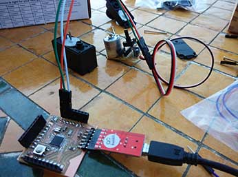
IDEAS TO RESOLVE THE PROJECT The project is intended to be resololved with as many as assignments of the FABLAB as possible. Along the weeks, I will try to adapt each of the steps to my own benefit in order to save time for the last weeks of the project resolution. - Building Model.- the building model will be done with the CNC machine. I will try for that week to have the pieces prepared to be cut in the machine and to assembly all of them together. - Mechanism.- the mechanism is thought to be built with the 3D printer. I want to make a chain and some gears that will connect all the louvers of my roof in series, and all of the afterwards into the engine that will move the whole mechanism. - The Louvers.- the louvers will be done the in the week of composites. This louvers will be as light as possible so the mechanism dos not suffer a lot when they are moved. As there will be many of them, a very light structure will be much more easy to move. - The Electronics.- the whole structure will be moved with an Arduino, and in order to have something working with it, I will do all the necessary boards along the FABLAB course for saving time in the last weeks. Some decisions will have to be made in the weeks of INPUTS, OUTPUTS and in NETWORKING AND COMMUNICATION. |
 |
 |
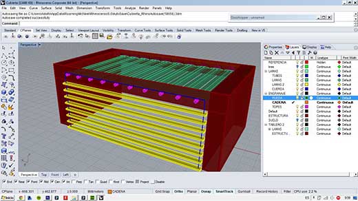
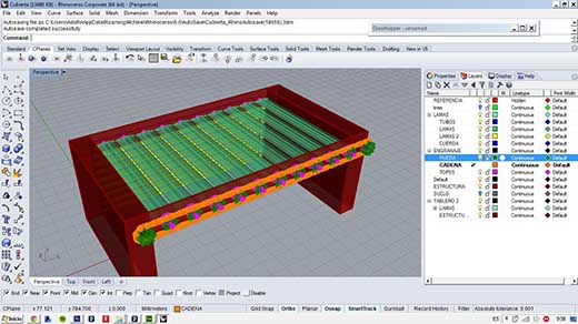
RESOLUTION OF THE PROJECT IN 3D: MOVEMENT OF THE LOUVERS During the past weeks I have trying to develop more the project in 3D to try to measure all the pieces that i will need to build. I needed to make the project in real scale so I could control everything. My delimitation was the design of the chain, that I will completely print in 3D and limitates my construction as I cannot print a smaller chain with the printer. Here are some images and videos of the design and movement of the project. |
 |
|
STRUCTURE OF THE PROJECT DEVELOPMENT According to the FabLab assignment structure, I decided from the very beggining of the course, to develop as much assignments as possible oriented always into the Final Project presentation. In this chapter, I will explain all the proccesses that I followed to accomplish each of the pieces that conform my final project.
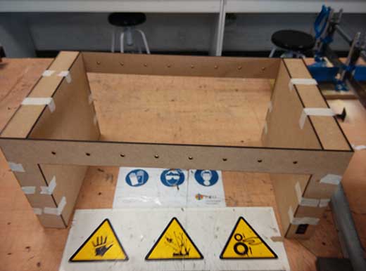
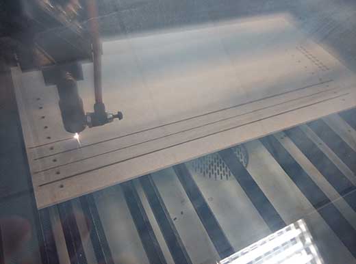
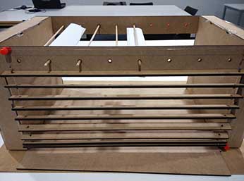
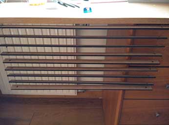
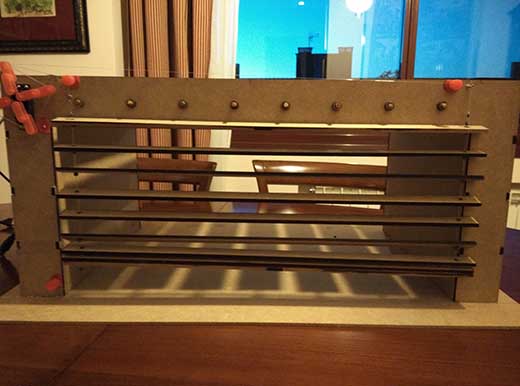
1. Wood structure of the "building": The portico structure is made out of wood, and it has been cut in the laser cut machine. The design has been made with Rhinoceros, and it has been done the Make2D to extract the exact dimensions of the boards to be cut. Some other pieces were cut in the laser cut machine aswell, as the horizontal louvers of the facade. It was necessary to remake some of the cuts as some of the pieces were not properly designed, but at tis very moment all the pieces fit perfectly between them and are strong enough to support the whole mechanisms needed. |
 |
 |
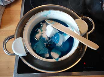
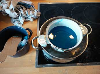
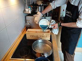
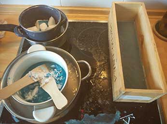
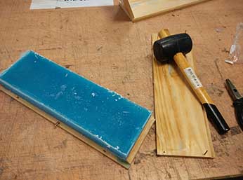
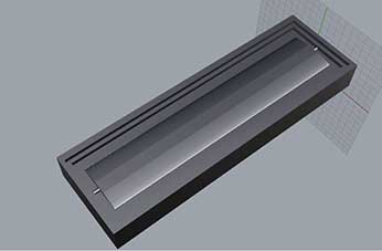
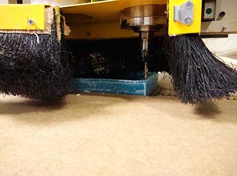
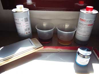
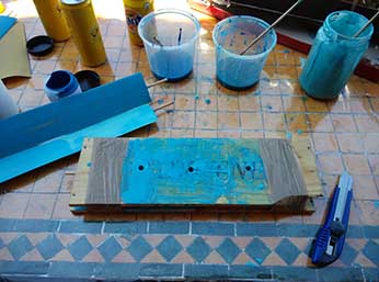
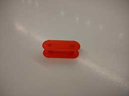
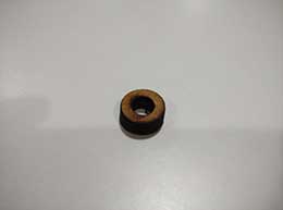
2. Louvers design: The louvers are being done with Molding and casting. As they are a piece that is going to be repeated many times, I thought that the best way to do them was to create two simmetrycal molds and place a stick between them to assemble all the structure and so when the louver rolls all the mechanism rolls with it. There was some incovenients doing the louvers with Modling and casting: - The main one was that the selling Wax pieces were not big enough to fit my louver that is 35 cm long, so I had to create a personalized wax piece to be scarved out with the CNC. As the industrial wax that we used in the Modling and casting assignment was very hard to melt. I had to do it with a different and softer wax. The best wax to do this part was actually to buty some chep candles and melt all of the wax in order to create my own wax piece. The process was a little bit tricky, but the result was very satisfactory and even the louvers are not finished yet, I think it will perfectly adapt to my idea. I used a box of wine to put the liquid wax and to serve as a mold for the wax piece. Here we can see some of the photos of the process.
|
||
 |
 |
 |
 |
 |
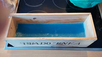 |
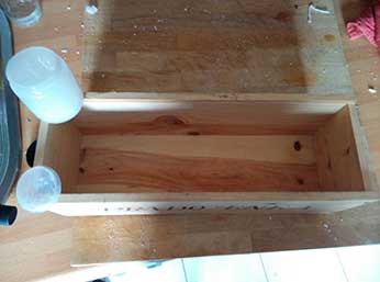
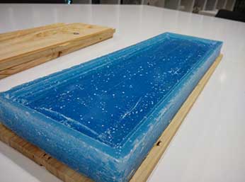
Once finished the wax piece, I had to wait for several hours so the wax got cold and fit perfectly to the box of wine. When the wax was cold, I could break the box in order to extract the piece of wax out of it. At the beggining I spread some vaseline all long the wine box, but it was not enough to extract the wax piece, and I did not want to break the wax piece, so i deided that the best way to extract was actually to break the box. When I extracted the wax piece, I realized that it was no completely plane on the top. It had reduce its density and there was much more wax on the walls of the box, and much less in the center of the piece. It may be caused by the adheration of the wax into the walls that may be the parts that got cold earlier. |
||
 |
 |
 |
 |
 |
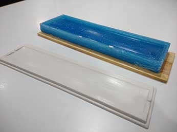 |
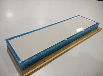
After doint two different molds for the pices, the first step is to attach the silicone molds to something solid and stable, so it does not bend when I am working with it. I used the same boards of from the box that fitted perfectly. Done that, we can start filling the louvers and leave them dry with the wooden stick on it. |
||
 |
 |
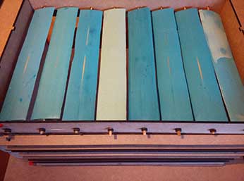 |
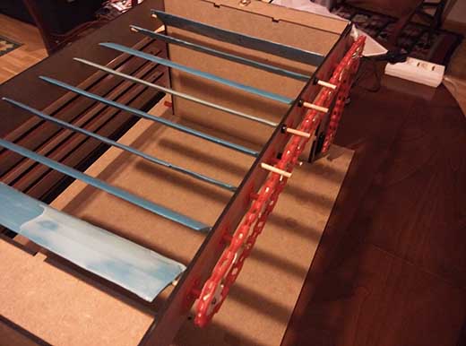
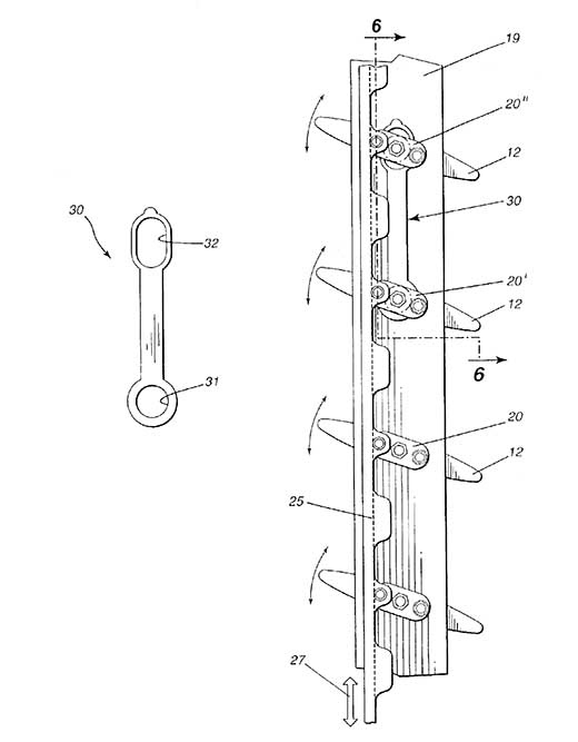
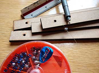
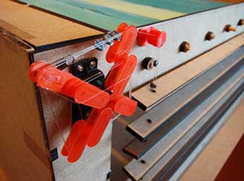
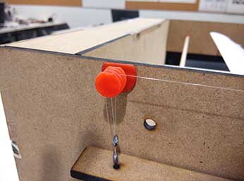
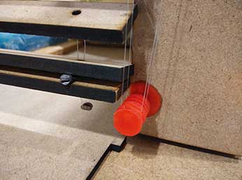
4. Vertical louvers of the facade This part of the project was added in the past weeks. I wanted to do something else with another servo, and I decided to free one of the facades to put vertical louvers that will move in the opposite movement as the horizontal louvers of the roof. While the roof louvers are rotating in one direction according to the phototransistor data, the facade lovers whill go up and down with the opposite data, and will open when the roof lovers close and viceversa. The facade louvers are done with the same wood as the structure. There were some facts that I did not considered at the beggining that I had to resolve on time when I was devoping the facade. I looked for a scheme of traditional louvers system, and I saw that I needed several cords and some of them had to have tops so they moved paralell constantly. As I was using nylon cord so it is as transparent as possible, I decided to follow the "fishing path" and use plumbum balls used for giving weight to the structure. It worked perfectly cause I could set the tops to each of the horizontal louvers.
|
||
 |
 |
 |
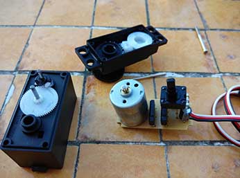
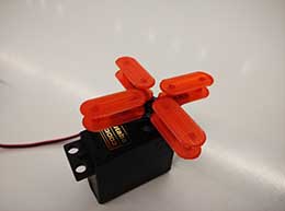
Continuous Rotation Servo As I was developing my project, I found out that the servo was limited to move only 180º, and I had to find another way to move this facade louvers as the gathering up cord was much larger that the maximum servo rotation. At the beggining I thought of doing something with a DC Engine or even a stepper, but I wanted to use one of the servos that I had in order not to buy any other component. I searched in internet and found out a site that explains perfectly how to manipulate the servo in order to rotate ore that 180º. (It is in spanish, but there are several places that explain it in english) I followed the instructions and I could change the servo to be controlled as a DC Engine, but I now have to find out the way to control the servo through the arduino code, not with the servo library but with PWM instructons.
|
||
 |
 |
 |
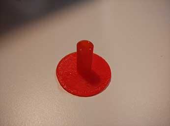
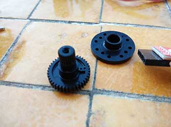
Even with the manipulated servo for the continuous rotation, I had some problems with the PWM programming and solving the problem of the heavy weight of the facade. Making them lighter would have solved the problem, but the result of the thick wood was much more beautiful for the model. With this problem, I had to design additional pieces for the Nylon wire gathering. I extracted the needed radius, to gather all the height of the model from the Circumference Length (Lc=2πR). With this radius, I could make a specific piece for the servo, so only with 180º rotation, the servo collects all the height of the model with Nylon cable. I 3D printed some important pieces as well, such as pulleys, and guides for the wood sticks so it |
||
 |
 |
 |
|
 |
 |
 |
| ARDUINO PROGRAMMING |
Even the final code is not yet finished, I have here the code that I am using to move both servos with the data collected from the phototransistor. /* Final Project Arduino Code _by Adolfo Gutiérrez The FABLAB Arduino Code is going to move two Servos according to the Photoresistor values collected. Control of two servos with a photoresistor board. #include <Servo.h> int DelayServos = 500; // Set the convenient value of the delay that Futaba S3003 Servos need int val; // variable to read the value from the analog pin int valores = 0; const int minLight=144; //set the minimum light that reads the photoresistor const int Photoresistor=A5; //set the photoresistor PIN
void setup() Servo1.attach(7); // Attaches the servo of the roof on pin 7 void loop() Data = analogRead(Photoresistor); Serial.print("Data: "); // Here we set the values that will move SERVO 1 (Roof Movement) delay(100); //We make a small pause value = analogRead(Photoresistor); // reads the value of the potentiometer (value between 0 and 1023) value = map(value, minLight, maxLight, 0, 179); // scale it to use it with the servo. This servo is forced to have a non-limited movement all along 180º } |
| PROCESS IMAGES OF THE PROJECT | |
|
 |